UART: Key Features and Applications in Embedded Systems
Overview: This article explores UART, an essential asynchronous communication protocol, detailing its features, advantages, limitations, and challenges in embedded systems and various industries.
Digital data may be sent between devices using parallel and serial data transmission. UART, a stand-alone integrated circuit, is used for serial data transfer across computers or secondary devices in digital circuits.
What is a UART?
UART stands for universal asynchronous receiver transmitter. It is a universal serial, 2-wire, asynchronous, full-duplex communication protocol that exchanges data between electronic devices. It is commonly used to implement onboard data transmission in embedded and IoT systems. Additionally, it is used to connect computers to external devices, like sensors, monitors, and printers.
Features and Advantages
A serial method of data transmission is where bits are sent sequentially, one after another, over a single communication channel. The term “2-wire” refers to the basic configuration comprising of transmitter (Tx) wire, a receiver (Rx) wire, and a common ground connection. It simplifies PCB design by requiring only two wires for communication, and it is a cost-effective solution in embedded systems.
Asynchronous communication means the transmitter and receiver do not have a shared clock signal. This allows devices with different clock rates to communicate effectively, as they can operate independently while maintaining a reliable data transfer. The data transmission format and baud rate between two data lines must match to accomplish serial communication. This makes them reliable over moderate distances without requiring synchronized clocks.
Unlike clock signals, UART relies on the baud rate to determine the timing of data bits. The baud rate defines the speed of data transmission and is expressed in bits per second (bps). The transmitting and receiving devices must use the same baud rate for successful communication. Common standard baud rates include 9600, 19200, 38400, and 115200 bps.
It supports three modes of communication: simplex, half-duplex, and full-duplex. Simplex communication allows data to flow in only one direction. Half-duplex communication allows data to flow in both directions but not simultaneously. Full-duplex communication allows data to flow in both directions simultaneously.
Structure and Working of UART
The Tx and Rx are the two pins in every UART device, as seen in Fig. 1. They serve as serial communication devices and are mostly utilized for data transmission and reception.
Fig. 1 Illustration of two UARTs communicating with each other. Source: Applied and Computational Engineering
As seen in Fig. 2, The transmitting UART1 module, which receives parallel data from its data bus, converts it into the serial format and sends it via its Tx pin. The receiving UART2 module, which receives serial data at its Rx pin, converts it back into parallel format and outputs it to its connected data bus. The Tx pin of UART1 is connected to the Rx pin of UART2, enabling serial communication between the two modules.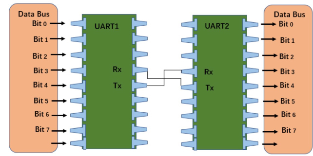
Fig. 2 Detailed illustration of two UARTs communicating with each other. Source: Applied and Computational Engineering
In UART, communication contains several components and essential steps that play a significant role, as seen in Fig. 3.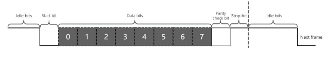
Fig. 3 Framework of UART showing the different bit types in sequence. Source: Applied and Computational Engineering
Idle Bit
The UART's transmission and reception lines are initially high, indicating that no data is transmitted and the line is idle.
Start Bit
Directly transferring data via UART may result in errors due to the lack of a uniform clock between the devices. Therefore, it is important to include a start bit. The start bit signals the beginning of data transmission and notifies the receiver that a word of data will be sent, forcing the receiver's clock to synchronize with the transmitter's clock. A low level on the UART line in the start bit indicates that data can be received.
Data Bits
The transmitter initiates communication by sending data at a particular frame. In UART communication, 5-8 bits (uses parity bit) or 9 bits (without parity bit) can be included in a single data transfer. For example, the initial transmission of the serial data begins with bit 0, which is the lowest bit, followed by bit 7, as shown in Fig. 2.
Parity Bit
The receiver may check for the parity bit when it receives all the data bits. It serves as an error-checking mechanism, helping to detect data corruption during transmission. Various errors can occur due to long transmission, variable baud rates, and electromagnetic radiation detected by parity bit. Then, the receiver looks for a stop bit.
Stop Bit
The stop bit indicates the end of the data frame, giving the receiver time to process the received information. The start bit is a low signal, while the stop bit is an active high signal. The start and stop bits are removed when the Rx pin reads the data frame. Finally, it sends the data to the CPU simultaneously or in parallel format.
Challenges
- Unlike protocols such as I2C and SPI, which can handle multiple devices on a single bus, UART limits it to two communicating devices at a time.
- Requires precise matching of baud rates between communicating devices.
- Not suitable for applications demanding high data throughput networks.
- Limited speed compared to high-speed protocols like SPI or I2C.
UART is the primary component that enables serial communication in computers and is often included in the peripheral devices of microprocessors. It facilitates communication between the host and auxiliary devices.
Summarizing the Key Points
-
UART is a universal, asynchronous, 2-wire communication protocol that simplifies data transmission between devices.
-
It supports three communication modes: simplex (one-way), half-duplex (two-way, non-simultaneous), and full-duplex (two-way, simultaneous).
-
Key components in UART communication include idle, start, data, parity, and stop bits, ensuring accurate data transmission.
-
Limitations of UART include the restriction of communication to two devices, baud rate matching, and lower speeds compared to other protocols.
Reference
Gong, J., Guo, W., & Sun, W. (2023). UART communication protocol frame format explanation and application. Applied and Computational Engineering, 14(1), 47–56. https://doi.org/10.54254/2755-2721/14/20230757
Xing, Y. (2024). Hardware circuit implementation of transmitter and receiver based on UART protocol. Applied and Computational Engineering, 72(1), 204–210. https://doi.org/10.54254/2755-2721/72/20241036
Kamath, A., Mendez, T., Ramya, S., & Nayak, S. G. (2022). Design and Implementation of Power-Efficient FSM-based UART. Journal of Physics Conference Series, 2161(1), 012052. https://doi.org/10.1088/1742-6596/2161/1/012052
Chandupatla, T., & Sotoudeh, H. (2024). UART IP core Design and Verification using the WISHBONE Interface. International Journal of Engineering and Computer Science, 13(10), 26492–26497. https://doi.org/10.18535/ijecs/v13i10.4906